
Technical perspective
Cement production combines dust, heavy shock loads, high temperatures, slow-speed gearing and continuous duty. A single plant may operate crushers, raw and finish mills, kiln drives, hydraulic power packs, compressors and mobile equipment, each producing different oil evidence and failure consequences.
Chem-Tech structures the programme by asset family rather than applying one panel to every bottle. Criticality, sump volume, filtration, speed, load and known failure modes determine the test package, sampling point and frequency. Results are trended with vibration, temperature, filter and maintenance data.
Article section
Control dust ingress without overlooking active wear
Silicon can indicate airborne dust, sealant or additive contribution depending on the oil and context. Particle count may be less suitable for very dark or heavily contaminated gear oils, while ferrography and PQ can reveal larger ferrous wear. A cement-plant interpretation must separate environmental contamination from component-generated debris.
Asset naming is essential. 'Gearbox oil' is not enough when the plant has dozens of units with different ratios, oils and sample points. Use a permanent equipment hierarchy and sampling port for every critical asset.
- Crusher or mill gearbox iron, PQ or vibration trend increases under load.
- Hydraulic particle counts rise after seal, hose or maintenance work.
- Dust, water or process material enters through breathers, seals or open transfer practices.
- Oil darkens or viscosity changes near kilns and other high-temperature zones.
Article section
Match the evidence to cement-plant asset families
Gearboxes need viscosity, water, elemental wear and larger ferrous-debris evidence. Hydraulic systems emphasise cleanliness, water and wear. Compressors require oxidation, acid and contamination monitoring. Mobile assets add soot, fuel dilution and base-number considerations.
Use alarms based on the same asset type and lubricant. A high value that is normal for a slow-speed open or heavily loaded gearbox should not be compared directly with a precision hydraulic system.
Crushers and mills
Wear debris, viscosity and contamination trends address shock-loaded gears and bearings.
Kiln drives
High-temperature oxidation, oil condition and large-particle evidence support outage planning.
Hydraulics
ISO cleanliness, water and wear trends protect pumps, valves and actuators.
Mobile fleet
Engine, axle, transmission and coolant evidence is kept separate by component.
Article section
Indicative cement-plant asset packages
Chem-Tech builds the test schedule from the plant asset register. These examples show how panels change by machine rather than by a generic 'oil analysis' label.
| Package | Use when | Indicative tests and methods | Decision supported |
|---|---|---|---|
| Crusher/mill gearbox | Critical enclosed gears and bearings | Viscosity — ASTM D445/D7042; water — ASTM D6304; ICP — ASTM D5185; PQ — ASTM D8184; ferrography — ASTM D7690 | Trend wear, dust and lubricant condition |
| Hydraulic systems | Kiln, mill and pack hydraulics | Particle count — ISO 4406; water; viscosity; ICP; TAN — ASTM D664 | Control cleanliness and component wear |
| Diesel mobile assets | Loaders, dumpers and quarry equipment | Viscosity; ICP; FTIR — ASTM E2412; soot — ASTM D7686; fuel dilution — ASTM D7593; TBN — ASTM D4739 | Monitor engines under dust and load |
Sampling frequency and alarms are set after criticality and baseline review. Accreditation is confirmed for each selected matrix, parameter and method.
Request a scope and package discussionArticle section
Engineer safe permanent sample points
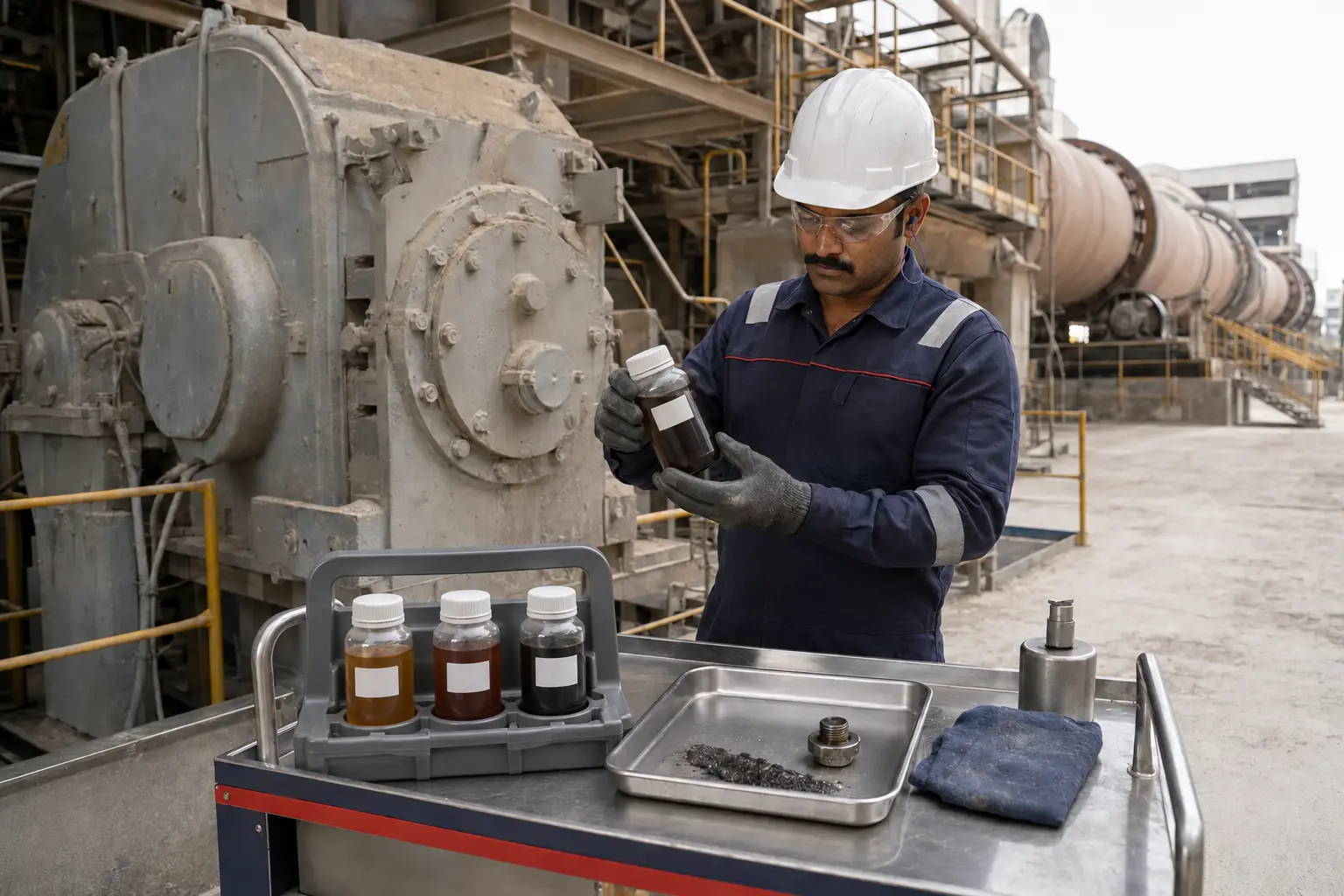
Sampling from drains during shutdown can delay decisions and add settled debris. Install appropriate live-zone points during planned maintenance where risk assessment permits.
- Use the plant tag, component, lubricant and sample-point ID on every bottle.
- Sample at comparable load and temperature before filter or oil changes.
- Keep transfer tools sealed from cement dust and do not reuse open funnels.
- Collect magnetic-plug, filter and deposit evidence separately during outages.
- Record lubrication additions, dust events and maintenance since the previous sample.
Article section
Turn the laboratory trend into a planned inspection
Use multi-parameter alarms to rank action: resample, check a breather, inspect a seal, review filtration, align with vibration, or plan gearbox inspection. Rising ferrous debris with vibration is more actionable than one isolated elemental value.
After repair, establish a fresh baseline rather than comparing indefinitely with the pre-repair population. Track avoided failures, lubricant life and inspection findings to refine the programme.
- Prioritise high-consequence kilns, mills, crushers and hydraulic systems.
- Use route-based sample collection with barcode or controlled asset identity.
- Hold joint oil, vibration and maintenance reviews for critical alarms.
- Verify contamination-control improvements through repeatable trends.
Apply this guidance